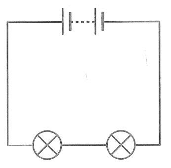
Use two 1.5 V electric cells in holders, two small lamps in holders, connecting wires and an ammeter. The cells and both lamps form the simple series circuit shown.
Look at the circuit diagram. Gather the components and build the circuit. Break the circuit at the point to be measured. Connect the ammeter in series at the break point to ensure that the current will flow through the ammeter. Measure and record the current at the following points: just after the battery of cells, between the two lamps, and before completing the circuit at the battery.
Use two 1.5 V electric cells in holders, two small lamps in holders, connecting wires and an ammeter. The cells and both lamps form the simple series circuit shown.
What current was measured just after the battery of cells?
Use two 1.5 V electric cells in holders, two small lamps in holders, connecting wires and an ammeter. The cells and both lamps form the simple series circuit shown.
How does the current change when measured at the different points in the circuit?
Use two 1.5 V electric cells in holders, two small lamps in holders, connecting wires and an ammeter. The cells and both lamps form the simple series circuit shown.
Based on what you have discovered about the current in a series circuit from your measurements, predict what the current will be when measured at the point between the two batteries. Test your hypothesis by taking the measurement.
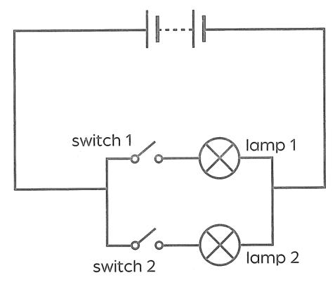
Use two 1.5 V electric cells in holders, two LED lamps or 3 V lamps, electrical wires and two switches (a breadboard is optional). The cells are in series; each lamp has its own switch in a separate parallel branch, as shown.
Look at the circuit diagram. Gather the components and build the circuit. Ensure that the circuit is complete and that all connections are secure before turning on the switches. Turn on switch 1. Observe and record the brightness of each lamp in the table. Turn on both switches. Observe and record the brightness of both lamps together. Record any changes in brightness between either or both lamps.
| Action | Observation of brightness of lamp |
|:-|:-|
| Turn on switch 1. | Lamp 1: ___; Lamp 2: ___ |
| Turn on switch 2. | Lamp 1: ___; Lamp 2: ___ |
Use two 1.5 V electric cells in holders, two LED lamps or 3 V lamps, electrical wires and two switches (a breadboard is optional). The cells are in series; each lamp has its own switch in a separate parallel branch, as shown.
Use two 1.5 V electric cells in holders, two LED lamps or 3 V lamps, electrical wires and two switches (a breadboard is optional). The cells are in series; each lamp has its own switch in a separate parallel branch, as shown.
What happens to the brightness of the lamps when both switches are on, compared to just one switch? Why do you think this is so?
Use two 1.5 V electric cells in holders, two LED lamps or 3 V lamps, electrical wires and two switches (a breadboard is optional). The cells are in series; each lamp has its own switch in a separate parallel branch, as shown.
Consider how switching one parallel lamp affects the brightness of the other. Why might this feature be useful in household circuits?
Use two 1.5 V electric cells in holders, two LED lamps or 3 V lamps, electrical wires and two switches (a breadboard is optional). The cells are in series; each lamp has its own switch in a separate parallel branch, as shown.
What would happen if one lamp burns out or is removed in a parallel circuit?
Use two 1.5 V electric cells in holders, two LED lamps or 3 V lamps, electrical wires and two switches (a breadboard is optional). The cells are in series; each lamp has its own switch in a separate parallel branch, as shown.
From your results, predict what will happen if you add a third lamp in parallel with the two you already have in your circuit. What is the best way to test your prediction?
Imagine that you have a portable music player that requires 6 V and 1 A or more to work. However, you do not have a single electrical cell that meets these requirements. Instead, you have the following:
- Four 1.5 V AA cells, each providing 0.5 A
- Three 2 V cells, each providing 0.5 A
Your task is to combine these electrical cells in series and/or parallel to achieve exactly 6 V and as close to 1 A or more to be able to power your music player.
Caution: Electronic devices are often sensitive to incorrect voltages. Do not experiment with voltages without supervision.
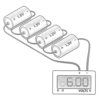
Look at the picture. Should you arrange the four 1.5 V AA cells in series or in parallel to create a total of 6 V? Explain your arrangement.
Imagine that you have a portable music player that requires 6 V and 1 A or more to work. However, you do not have a single electrical cell that meets these requirements. Instead, you have the following:
- Four 1.5 V AA cells, each providing 0.5 A
- Three 2 V cells, each providing 0.5 A
Your task is to combine these electrical cells in series and/or parallel to achieve exactly 6 V and as close to 1 A or more to be able to power your music player.
Caution: Electronic devices are often sensitive to incorrect voltages. Do not experiment with voltages without supervision.
The four AA cells are arranged in series to give 6 V. What will the total current available from the AA cells be when they are arranged as described in question 2? Is this enough current to make the music player work?
Imagine that you have a portable music player that requires 6 V and 1 A or more to work. However, you do not have a single electrical cell that meets these requirements. Instead, you have the following:
- Four 1.5 V AA cells, each providing 0.5 A
- Three 2 V cells, each providing 0.5 A
Your task is to combine these electrical cells in series and/or parallel to achieve exactly 6 V and as close to 1 A or more to be able to power your music player.
Caution: Electronic devices are often sensitive to incorrect voltages. Do not experiment with voltages without supervision.
If you connect the three 2 V cells in series to create a total of 6 V, would you be able to use them to make the music player work? Explain your answer.
Imagine that you have a portable music player that requires 6 V and 1 A or more to work. However, you do not have a single electrical cell that meets these requirements. Instead, you have the following:
- Four 1.5 V AA cells, each providing 0.5 A
- Three 2 V cells, each providing 0.5 A
Your task is to combine these electrical cells in series and/or parallel to achieve exactly 6 V and as close to 1 A or more to be able to power your music player.
Caution: Electronic devices are often sensitive to incorrect voltages. Do not experiment with voltages without supervision.
The previous configurations are one series string of four 1.5 V AA cells and another series string of three 2 V cells. Given your configurations in the previous questions, how can you use both types of electrical cells to meet the music player’s requirements?
Imagine that you have a portable music player that requires 6 V and 1 A or more to work. However, you do not have a single electrical cell that meets these requirements. Instead, you have the following:
- Four 1.5 V AA cells, each providing 0.5 A
- Three 2 V cells, each providing 0.5 A
Your task is to combine these electrical cells in series and/or parallel to achieve exactly 6 V and as close to 1 A or more to be able to power your music player.
Caution: Electronic devices are often sensitive to incorrect voltages. Do not experiment with voltages without supervision.
A proposed configuration has the four 1.5 V cells in one series string and the three 2 V cells in another series string, with the two strings connected in parallel with matching polarity. Explain your answer.
Materials: three resistors (100 Ω, 200 Ω, 300 Ω), a 9 V battery and battery clip, connecting wires, multimeter, breadboard (optional).
The three resistors are connected in series. Connect one end of the series to the positive terminal of the battery and the other end to the negative terminal. Use the multimeter to measure and record the current flowing through the circuit.
Materials: three resistors (100 Ω, 200 Ω, 300 Ω), a 9 V battery and battery clip, connecting wires, multimeter, breadboard (optional).
The three resistors were connected in series and their total resistance measured. What is the total resistance you measured? How does this compare to the sum of the individual resistances?
Materials: three resistors (100 Ω, 200 Ω, 300 Ω), a 9 V battery and battery clip, connecting wires, multimeter, breadboard (optional).
The 100 Ω, 200 Ω and 300 Ω resistors are in series across the 9 V battery; total resistance and current have been measured with a multimeter. Given the resistance of the circuit that you have already measured and the voltage of the battery, calculate the current flow using Ohm’s Law. Compare your calculated result with the measurement you made with your multimeter.
Materials: three resistors (100 Ω, 200 Ω, 300 Ω), a 9 V battery and battery clip, connecting wires, multimeter, breadboard (optional).
In this series circuit, imagine replacing one of the fixed resistors with a variable resistor. How would adjusting the resistance of the variable resistor affect the total resistance and the current in the circuit?